- Details
| Parameter | Accuracy | Instrument |
|
Surface Figure |
0.05 waves PV |
12" Zygo GPI-xp |
| Surface Roughness | +/- 1 angstrom | Wyko & Chapman Surface Profilers |
| Reflectance | +0.5 %R | Perkin Elmer 1050 Perkin Elmer Spectrum Optica 100 |
| Mechanical Dimensions | 1.0 microns | Zeiss CMM Micro Height Indicators |
| Angular | 0.5 arc second 0.25 arc second |
Nikon Autocollimator AA Gauge Indexers |
| Perpendicularity |
0.4 arc second |
Nikon Autocollimator |
| Surface Inspection per mil spec. | MIL-O-13830 | High Intensity Lights Scratch/Dig Standards |
| Environmental per mil spec. | MIL-C-48497, MIL-C-675, MIL-F-48416 | Temp/Humidity Chambers |
- Details
| Type | Specification | Notes |
|
Nickel Plating |
AMS2404F |
Replaced AMS-C-26074 and MIL-C-260. Class 1,2,3,4. |
|
Gold Plating (Technic Gold 25) |
MIL-G-45204C |
99.7% (Type I) and 99.0% (Type II) gold minimum. Grade C (Knoop Hardness of 130-200). Class 00 (minimum 0.00002 inches thick). |
|
Chromate (Irridite14-2) |
MIL-DTL-5541F |
Replaced MIL-C-5541E. Type 1 for compositions containing hexavalent chromium. Class 1A for maximum protection against corrosion, painted or unpainted. Class 3 for protection against corrosion where low electrical resistance is required. |
- Details
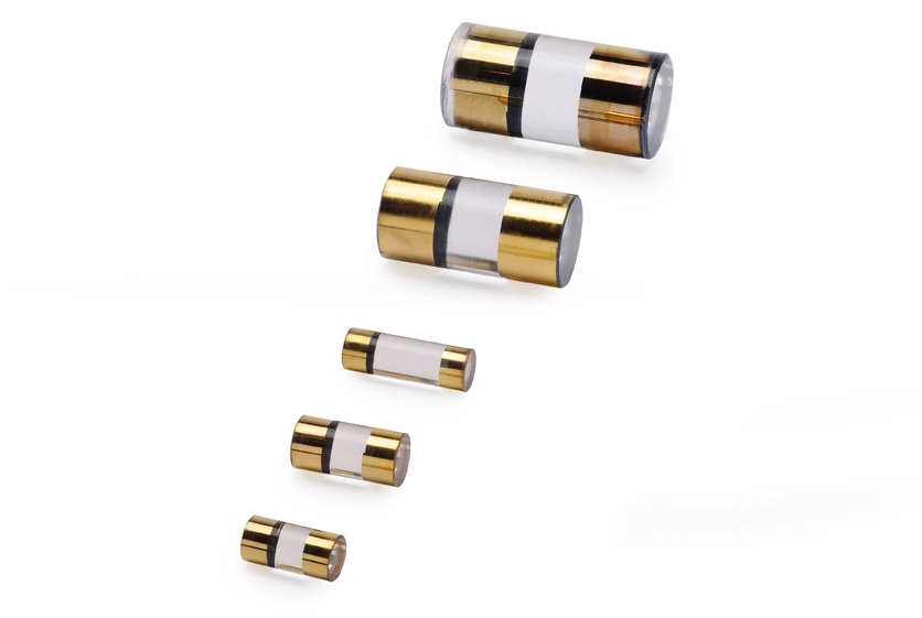
 The Pockels cell should be rotationally oriented so that the fast and slow axes that are induced by application of a voltage to the Pockels cell are at ±45º to the polarization direction of the input light beam. This can be done by rotation of the Pockels cell so that the direction in which the electrode contacts point is aligned either parallel or perpendicular to the polarization direction of the laser. For example, if the electrodes point straight up, then either vertically polarized or horizontally polarized light will be rotated by 90º when the half-wave voltage is applied to the electrode contacts.
For proper operation, one will need to align the optic axis of the crystal to the laser beam direction. With no voltage applied to the crystal, the optic axis direction can be found by using, in order, a polarized input beam, scatterer, crystal, analyzer, and viewing card. When the analyzer (polarizer) is set to pass light of a polarization perpendicular to that of the input polarization direction, the transmitted intensity pattern will consist of concentric light and dark rings with a single superimposed vertical dark line and a single horizontal dark line along the direction of the polarizer and analyzer pass directions. The scatterer, which can be a piece of lens tissue placed close to the crystal input face, produces the off axis rays that allow one to see the interference pattern of light and dark on the viewing card. Otherwise, the low-divergence laser beam would sample only a small portion of the entire field pattern so that the transmitted laser beam would be a uniform lightness or darkness. By tilting the crystal appropriately, one can align the center of the interference pattern, and hence the optic axis, to the direction of the laser beam.
Typically, the Pockels cell is used in either a half-wave or a quarter-wave mode.
When used in the half-wave mode, the Q-switch rotates the polarization of the input beam by ninety degrees. More generally, a linear polarization is rotated by twice the angle between the polarization direction of the light and a fast or slow axis of the crystal. Hence, any desired rotation can be attained while operating the Pockels cell at the half-wave voltage.
When used in the quarter wave mode, the Q-switch converts the linear polarization of the input beam into circularly polarized light. By using a mirror to send the beam back through the crystal along the same path while the quarter-wave voltage is applied, the polarization of the outgoing light is at ninety degrees to the polarization of the incoming light. The quarter-wave mode of operation has the advantage that the applied voltage is one-half the voltage required for half-wave mode operation.
Category: Applied Optics
- Details
| Parameter | Accuracy | Instrument |
|
Surface Figure |
0.005 waves |
6 Zygo Interferometers up to 18" 12" VERIFIRE |
| Spectral Characteristics |
+/- 0.05 %T |
Hitachi U-4100 Perkin Elmer 1600 FTIR Perkin Elmer Spectrum Optica 100 |
| Thickness Dimension |
+0.05 microns |
Heidenhain Drop-Dial Indicator |
| Parallelism 1 arc second | 1 arc second |
Zygo Interferometer |
| Prism angles |
2 sec |
Trioptics Prism Master |
| Scratch & Dig | MIL-PRF-13830-ISO 10110 | Standard lighting, high Intensity fiber optics lighting S&D Standards |
| Environmental per mil spec. | Hot, cold, humidity, salt fog per mil sec. MIL-C-48497, MIL-C-675, MIL-F-48416 |
Tenney Micro-Temm II, BMA, Associated |
| Crystal Orientation | +/- 5 arc second | Double Crystal X-Ray Spectrometer |